
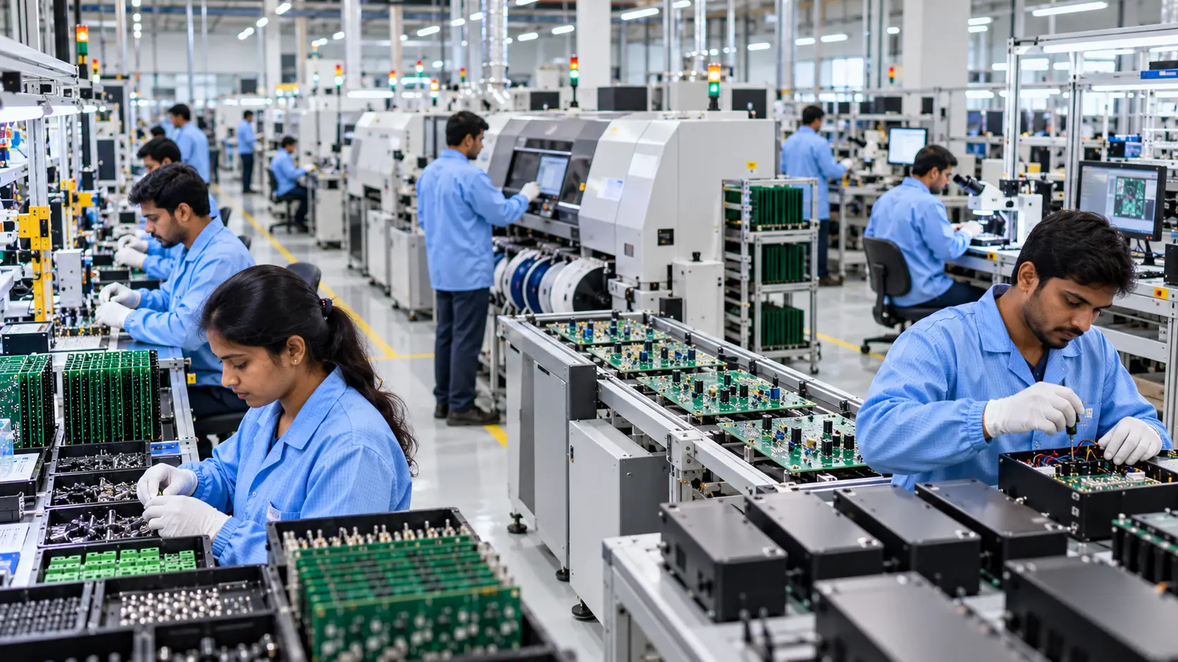
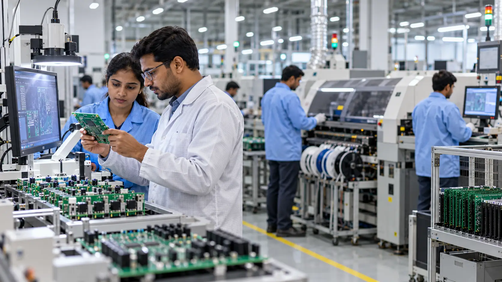
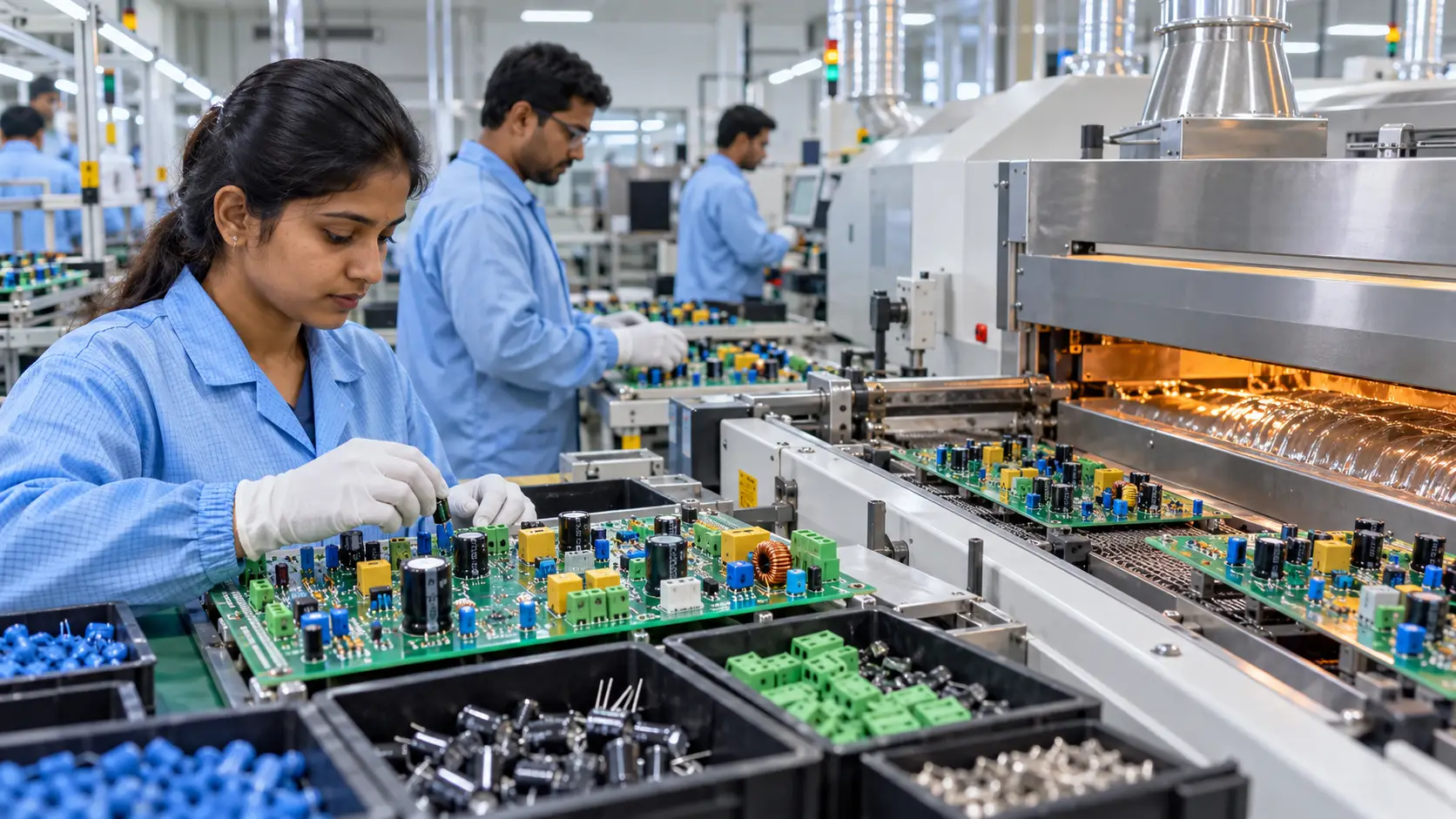
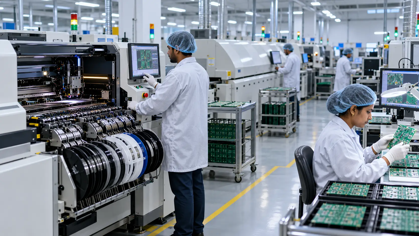
PCB assembly quality testing helps verify that an assembled printed circuit board meets the required manufacturing, electrical and functional conditions before moving further through production.
Depending on the PCB design and product requirements, quality evaluation may involve Automated Optical Inspection (AOI), In-Circuit Testing (ICT), functional testing and reliability checks. Each method addresses different aspects of PCB quality.
What Is PCB Assembly Quality Testing?
PCB assembly quality testing is the process of inspecting and evaluating an assembled printed circuit board to identify manufacturing issues and verify that the assembly meets the applicable requirements.
Quality testing can begin during the assembly process rather than only after the board is completely manufactured. Different inspection and testing methods can be applied at different stages to identify issues related to component placement, soldering, electrical connections and product functionality.
The appropriate testing strategy depends on the PCB design, component configuration, production volume and requirements of the finished product.
Why Is PCB Assembly Testing Important?
A PCB contains multiple components and electrical connections that must work together according to the product design. An issue with component placement, soldering or an electrical connection can affect the performance of the completed assembly.
Testing and inspection help manufacturers identify potential issues before the PCB moves further through production or becomes part of the finished product.
A structured quality process can also help manufacturers monitor production consistency and identify recurring manufacturing issues that may require process improvement.
PCB Assembly Inspection vs Testing
Inspection and testing are related but serve different purposes.
Inspection generally involves examining the physical assembly to identify visible or measurable manufacturing conditions. This can include component placement, solder paste application and soldering-related conditions.
Testing evaluates electrical behaviour, circuit connections or product functionality according to the applicable test requirements.
Using the appropriate combination of inspection and testing methods provides a broader view of PCB assembly quality than relying on a single check.
Automated Optical Inspection (AOI)
Automated Optical Inspection, commonly known as AOI, uses automated imaging and software-based analysis to inspect a PCB assembly for specific visible manufacturing conditions.
AOI can be used to examine aspects such as component presence, component placement, orientation and soldering-related conditions that can be detected visually.
Because AOI is automated, it can support repeatable inspection across production volumes while helping identify boards that require further investigation.
What Does AOI Check?
The exact inspection capability depends on the AOI system and the PCB being inspected. Depending on the setup, AOI can identify conditions such as:
- Missing components
- Incorrect component placement
- Incorrect component orientation
- Visible soldering issues
- Component-related assembly conditions
AOI is primarily an inspection method. A board passing optical inspection does not automatically establish that every electrical or functional requirement has been satisfied. Additional testing may therefore be required.
In-Circuit Testing (ICT)
In-Circuit Testing, or ICT, is an electrical testing method used to evaluate specific characteristics of an assembled PCB. It can be used to check electrical connections and individual circuit elements according to the test configuration developed for the board.
ICT can help identify certain manufacturing faults that may not be visible through optical inspection alone.
The effectiveness and scope of ICT depend on the PCB design, test points, test fixture and requirements of the product. Not every PCB is equally suited to the same ICT approach.
What Can ICT Help Identify?
Depending on the test design, ICT can help identify conditions such as:
- Open electrical connections
- Short circuits
- Incorrect component values
- Component-related electrical faults
- Connection and assembly issues
ICT is therefore complementary to visual inspection because it evaluates electrical characteristics that may not be visible during an optical inspection.
Functional Testing
Functional testing evaluates whether the assembled electronic product or PCB performs its intended functions under defined test conditions.
While AOI focuses on physical assembly conditions and ICT can evaluate specific electrical characteristics, functional testing considers the behaviour of the completed circuit or product.
The exact functional test depends on what the product is designed to do. A telecommunications device, IT hardware product, wearable device and industrial electronic system can each require different functional test procedures.
Why Functional Testing Matters
Functional testing can help identify problems that may not be apparent through visual inspection or individual electrical checks. A PCB can have correctly positioned components and apparently acceptable solder joints while still failing to perform the required function.
Functional testing therefore provides an additional level of verification based on the actual operating requirements of the product.
PCB Reliability Checks
Reliability checks consider whether an electronic assembly can maintain the required performance under the conditions for which it is designed.
The appropriate reliability checks depend on the product, application and manufacturing requirements. Factors that may need consideration include electrical performance, mechanical conditions, thermal exposure, environmental conditions and expected operating life.
Reliability evaluation should therefore be defined according to the actual product requirements rather than applying the same testing programme to every PCB.
Common PCB Assembly Quality Issues
PCB assembly quality checks are designed to identify different types of manufacturing issues. Some common categories include:
- Component placement issues: Components may be missing, incorrectly positioned or incorrectly oriented.
- Soldering issues: Solder joints may not meet the required assembly conditions.
- Open connections: An intended electrical connection may not be properly established.
- Short circuits: Unintended electrical connections can occur between conductive points.
- Incorrect components: A component may not match the required specification or board configuration.
- Functional failures: The completed circuit may not perform its intended function.
Different testing methods address different categories of potential issues, which is why a combination of appropriate inspection and testing methods can be valuable.
How PCB Assembly Quality Testing Works as a Process
PCB quality testing is most effective when inspection and testing are integrated into the manufacturing process rather than treated as a single final check. The exact sequence depends on the PCB design, product requirements and manufacturing process.
- Process Preparation: Quality requirements and testing methods are defined according to the PCB and product.
- In-Process Inspection: Inspection methods identify potential assembly issues before the board moves further through production.
- Electrical and Functional Testing: Applicable tests evaluate circuit characteristics and confirm that the assembly performs its intended functions.
- Reliability Evaluation: Where required, additional checks assess performance under relevant operating or environmental conditions.
- Corrective Action: Identified manufacturing issues are investigated and the relevant production process is reviewed to help prevent recurrence.
Quality Testing in SMT Assembly
Surface Mount Technology introduces specific inspection requirements because modern PCBs can contain small components and fine-pitch placements.
Inspection can begin with solder paste application before component placement and continue through component placement and reflow soldering. Depending on the manufacturing setup, solder paste inspection, optical inspection and other quality checks can be used at relevant stages.
OEL’s SMT manufacturing capability includes Surface Mount Technology with 3D solder paste inspection and vision processing for part recognition.
The specific inspection and testing approach should always be aligned with the PCB design and manufacturing requirements.
Quality Testing in Through Hole and Mixed-Technology Assembly
Through hole assembly introduces different manufacturing considerations because component leads pass through holes in the PCB before soldering.
Inspection and testing need to account for component insertion, soldering and the interaction between through hole and surface-mounted components when both technologies are used on the same PCB.
For mixed-technology assemblies, the quality process should consider the complete board rather than treating SMT and through hole stages as completely independent operations.
How to Choose a PCB Assembly Partner Based on Quality
When evaluating a PCB assembly manufacturer, businesses should understand how quality is managed throughout the manufacturing process rather than simply asking whether the company performs final inspection.
Important questions include:
- What inspection methods are used during PCB assembly?
- How are component placement and soldering checked?
- What electrical testing capabilities are available for the product?
- How is functional testing defined and performed?
- How are manufacturing issues documented and addressed?
- Which quality and compliance requirements apply to the manufacturing operation?
- Can the testing process be adapted to the specific PCB and product requirements?
The answers should be evaluated in the context of the actual product rather than based only on a list of testing technologies.
Quality and Compliance in Electronics Manufacturing
PCB assembly quality is part of a broader electronics manufacturing quality framework. Manufacturing processes, inspection, testing, documentation and compliance requirements all contribute to the overall production environment.
Businesses should review the quality and compliance information provided by an electronics manufacturing company and understand which standards and certifications are relevant to their product and supply chain.
OEL maintains a dedicated quality and compliance framework covering recognised quality, environmental and ESD-related requirements.
OEL’s Approach to PCB Assembly Quality
OEL integrates quality checks into its electronics manufacturing processes across relevant stages of production. Its manufacturing capabilities include SMT, Manual Insertion, Final Assembly, Testing and Packaging, and New Product Introduction.
For SMT production, OEL’s capabilities include 3D solder paste inspection and vision processing for part recognition. Its broader manufacturing setup supports different stages of electronics production according to product and process requirements.
Businesses can explore OEL’s electronics manufacturing services to understand its broader manufacturing capabilities and production processes.
Frequently Asked Questions
What is PCB assembly quality testing?
PCB assembly quality testing is the process of inspecting and testing an assembled printed circuit board to identify manufacturing issues and verify applicable electrical, functional and quality requirements.
What is AOI in PCB assembly?
AOI (Automated Optical Inspection) uses automated imaging and software-based analysis to inspect PCB assemblies for visible conditions such as component placement, orientation and certain soldering-related issues.
What is ICT testing in PCB assembly?
ICT (In-Circuit Testing) is an electrical testing method used to evaluate specific characteristics of an assembled PCB according to its defined test configuration.
What is functional testing?
Functional testing evaluates whether an assembled PCB or electronic product performs its intended functions under defined test conditions.
Is AOI enough to test a PCB?
No. AOI is primarily an optical inspection method, so additional electrical, functional or reliability testing may be required depending on the product and its requirements.
Why is PCB reliability testing important?
Reliability checks help evaluate whether an electronic assembly can maintain the required performance under its intended operating conditions. The appropriate checks depend on the product and its requirements.
Does OEL provide PCB assembly and testing capabilities?
Yes. OEL provides electronics manufacturing capabilities covering SMT, Manual Insertion, Final Assembly, Testing and Packaging, and New Product Introduction, with SMT capabilities including 3D solder paste inspection and vision processing for part recognition.
Conclusion
PCB assembly quality cannot be established through a single inspection or testing method. AOI, ICT, functional testing and reliability checks address different aspects of PCB quality and can be combined according to the requirements of the product.
The appropriate testing strategy depends on the PCB design, components, manufacturing process, production volume and intended application. Businesses evaluating a PCB assembly partner should therefore look beyond individual testing technologies and understand how quality is managed throughout manufacturing.
OEL brings together electronics manufacturing capabilities across SMT, Manual Insertion, FATP and NPI, supported by quality and inspection processes relevant to its manufacturing operations.